Requirements
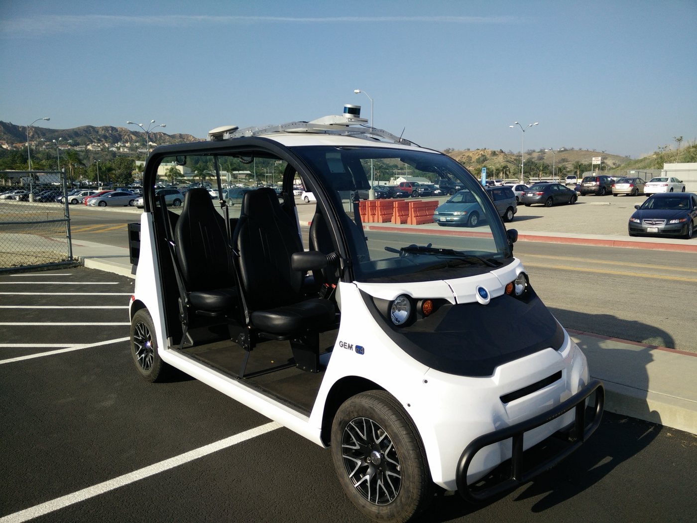
The system had to run high-level software on a powerful Linux computer with ROS, talk to the vehicle’s custom actuators (each needing its own position, force and velocity control), and stop the vehicle safely if anything failed catastrophically.
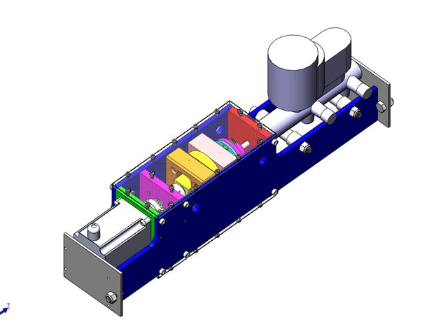
At shuttle speeds our main safety manoeuvre was simply to brake hard and stop within 10 feet. Two mechanical brakes made that possible: a proportional main brake for normal driving, and a fully independent, spring-loaded, normally-closed emergency brake held off by an electromagnet.
MVP in 45 days
The first version had to be a working demo within 45 days, so it used an off-the-shelf ruggedized Linux computer, off-the-shelf power conditioning, RS232 motor drivers (hard to introspect and control) and PCIe I/O cards. All software, including safety, ran on that one non-real-time computer.
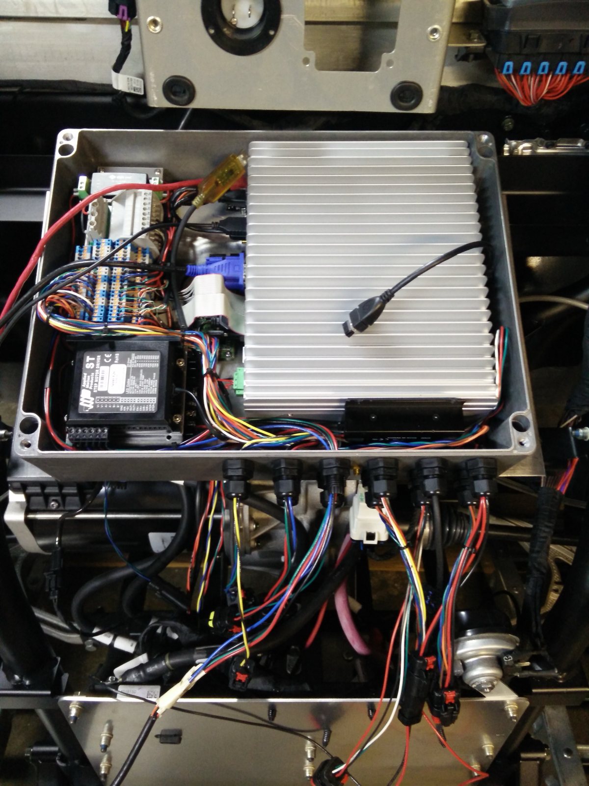
It worked for demos and testing, with a safety driver always ready to hit an e-stop that cut power to everything, including the e-brake magnet.
In-house design
Next came the first in-house system, designed to the requirements of an initial commercial product:
- Real-time microcontrollers for the steering and brake drivers, for faster response and better control of position, velocity and acceleration.
- Watchdog monitoring by multiple independent systems, each able to fire the emergency brake or apply the main brake.
- Hardware reliability and isolation, so no single point of failure could disable the emergency stop.
- Simpler interfaces and fewer separate modules, waterproof connections, and room to expand without a new main board.
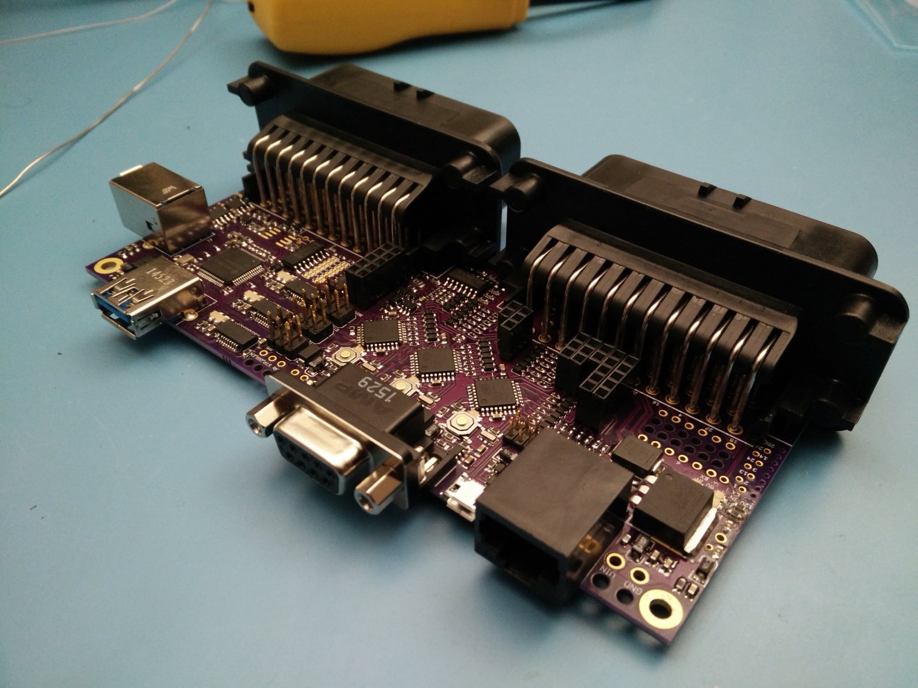
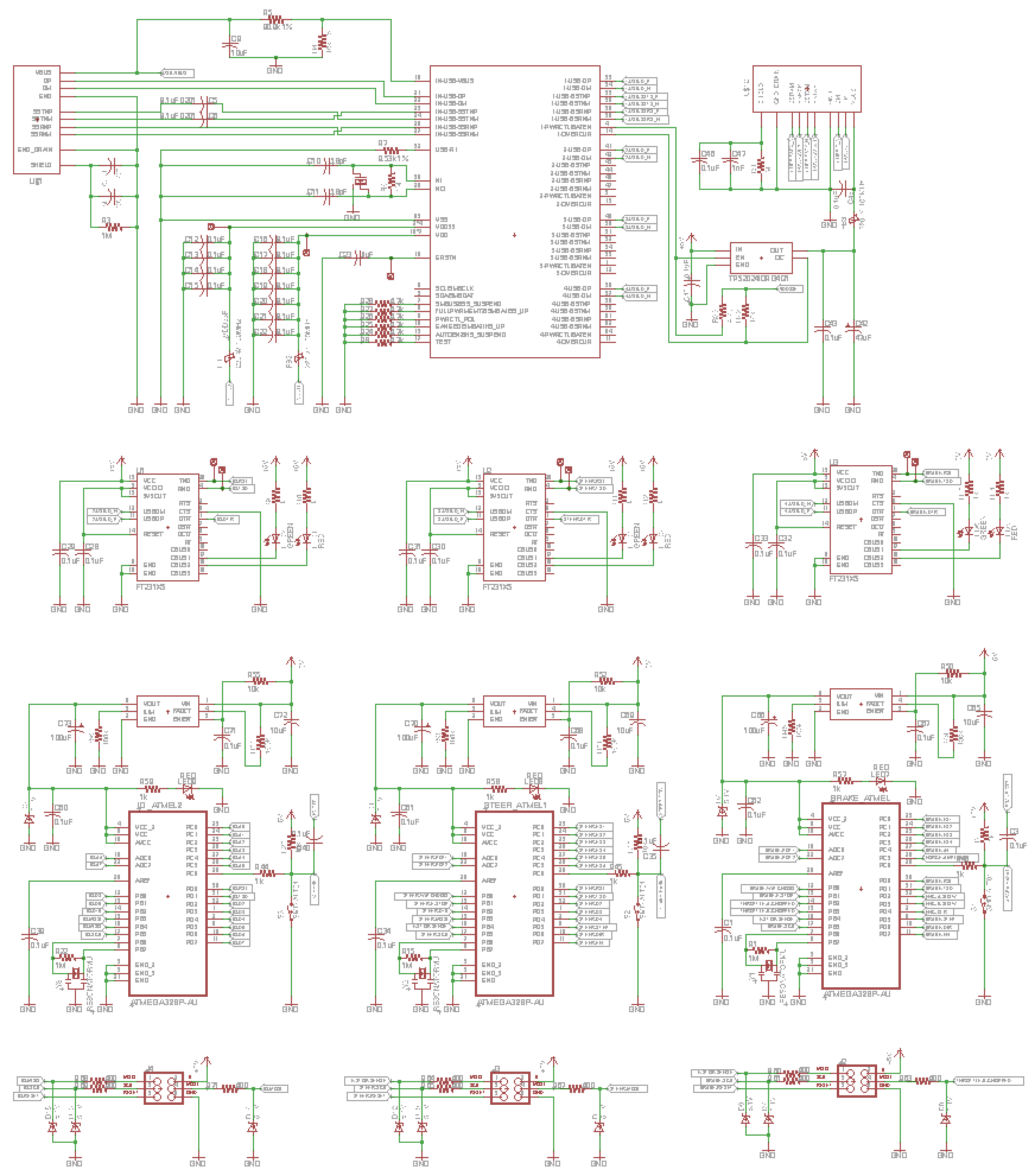
The main board carried three automotive-grade ATmega328Ps: one for steering, one for throttle and brake, and one for peripherals such as turn signals. An automotive USB hub linked all three to the Linux computer over serial, which also let us push new firmware through a bootloader. In the schematic, the hub is at the top, a USB-to-serial chip for each microcontroller sits in the middle, and the peripheral, steering and brake microcontrollers run along the bottom, left to right.
Control path
- ComputeLinux computerROS · high-level autonomy
- BusAutomotive USB hubSerial to every MCU · firmware updates
- Real-timeSteering MCUHand-wheel angle inThrottle / brake MCUVelocity control on boardPeripheral MCUTurn signals, expansion
- ActuatorsSteering motor driver2 rotation sensorsBrake driver + throttle linesForce sensor · wheel encoderDaughterboard headerPins broken out
Fail-safe design
The steering and throttle/brake chips each fed a dedicated watchdog IC with a square wave. If either stopped, basic transistor logic cut power to the e-brake magnet. Either chip could also trigger the brake itself on an internal fault or if the checksum handshake between the two chips failed.
Current sensing on the magnet showed whether it was powered and whether its steel block was still seated. A triggered e-brake also pulled both throttle lines to ground, faulting the vehicle’s own controller so it shorted the motor windings for extra braking.
Fail-safe chain
- MonitorsSteering MCUThrottle / brake MCU
- WatchdogWatchdog ICsEach fed a square wave · checksum handshake between MCUs
- SwitchTransistor logicCuts magnet power on any fault
- Fail-safe actionE-brake electromagnetUnpowered = full brakeThrottle lines → groundFaults the EV controller; motor braking
Sensing & protection
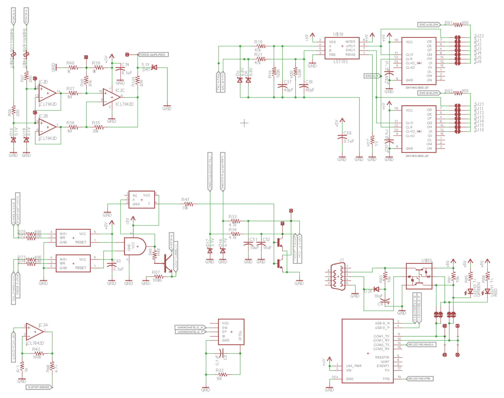
A differential amplifier read the brake force sensor’s Wheatstone bridge. A counter with a selectable pick-off point down-sampled the wheel encoder to cut interrupt load. The board also hosted the GPS, which fed a PPS signal to the Velodyne lidar. In the sensor schematic, the force amplifier is top left, the encoder circuit top right and the GPS bottom right; the watchdog logic for the e-brake magnet and the throttle-grounding transistors run across the middle.
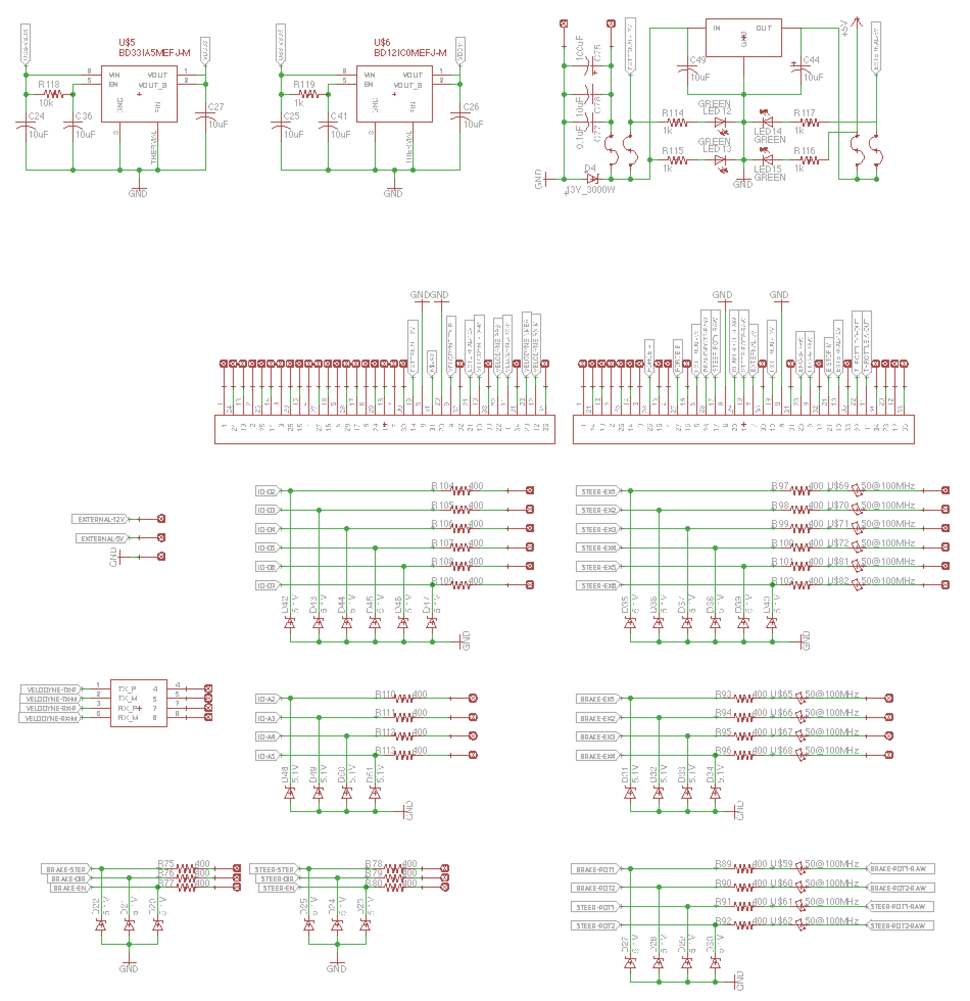
Every microcontroller I/O had over-voltage diodes, series resistors and, where needed, ferrite beads, with independent fuses, reverse-polarity and over-current protection across the board. The board would have sat in a waterproof enclosure with the Linux computer, GPS module and motor drivers, its two large connectors passing through the wall to carry every signal to the sensors and actuators outside.
Status at the pivot
We pivoted to Embark mid-way through. By then the first revision of the main PCB was built and its subsystems tested successfully. Firmware had started (mostly a custom stepper driver with acceleration and deceleration ramps) but wasn’t yet demonstrated.