Approach
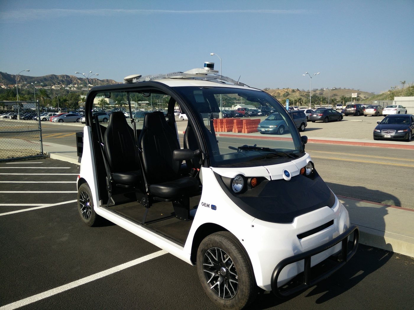
Both Varden prototypes were built on existing low-speed electric vehicles, so throttle was easy: an analog voltage imitating the pedal’s potentiometers. Brake and steering needed custom hardware.
Off-the-shelf options either worked through the pedal, visible to passengers and short of our safety criteria, or couldn’t produce 350 lb without being huge or expensive. Everything had to be fail-safe rather than fail-operational: if one actuator failed, another brake could stop the vehicle.
With about three weeks to get it all working, I designed every part to be machined by hand on manual equipment. Had we not pivoted, all three designs would have gone through another revision.
Brake
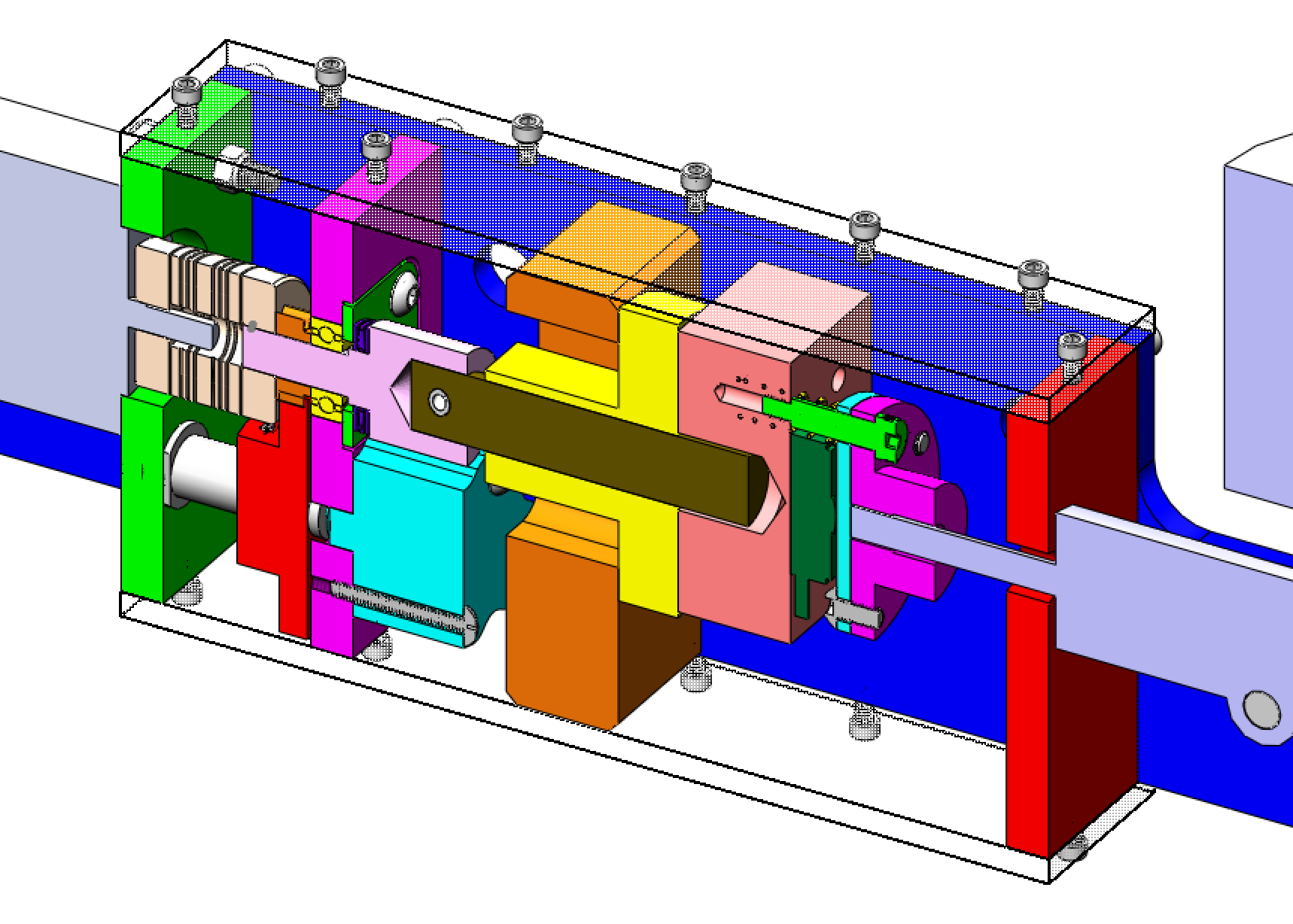
A stepper motor drives a ball screw that pushes the hydraulic master cylinder, positioning it from a position-to-force map. The motor runs open loop; a dual-channel contactless potentiometer checks for skipped steps, and a force sensor corrects the position and slowly re-fits the map.
In the cross section, the motor (off to the left) turns a machined shaft (light pink) through a flexible coupling, on radial and thrust bearings that take the brake’s full load. A small gear (orange) keeps the potentiometer under one turn. The ball screw (brown) drives a ball nut (yellow) held between a Delrin block (orange) that slides along the enclosure walls and an aluminium block (salmon) carrying the force sensor (dark green) behind a stainless disk (light blue) at the piston.
Brake actuator: control
- Brake commandTarget braking force
- Force → position mapRe-fit from force data over time
- Stepper motorOpen loop to position
- Ball screwRotary → linear
- Master cylinder0.5″ stroke · 50–350 lb
↺ potentiometer + force-sensor checks
Steering
The worst case for steering is a sudden turn too fast to react to, so I capped it at one hand-wheel turn per second. Driving the same stepper through a ~30:1 gearbox gives enough torque up to exactly that speed; any faster and the motor stalls.
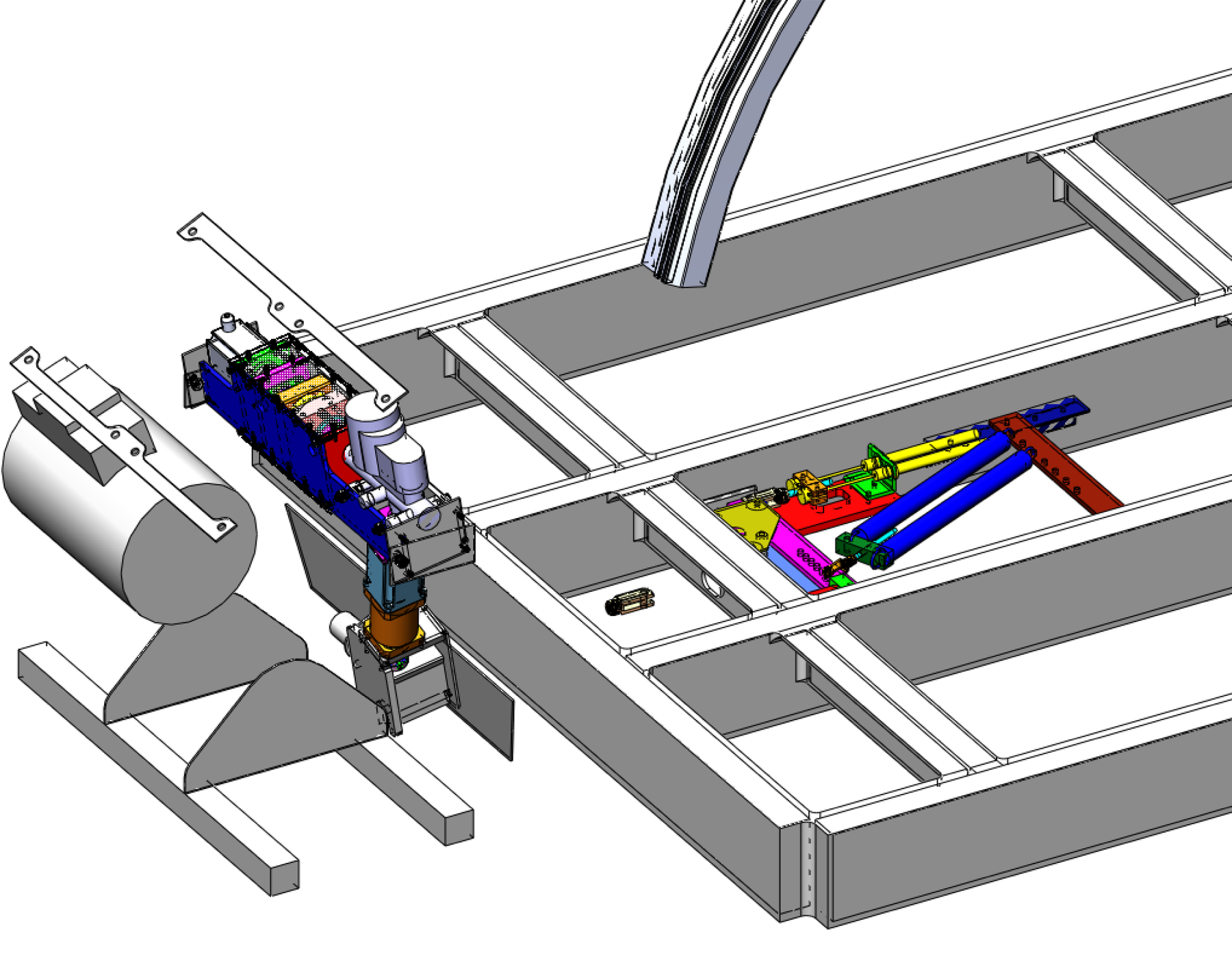
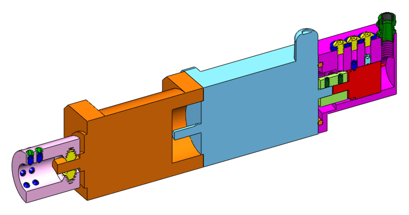
For the demos we removed the hand-wheel entirely and drove with a joystick, which also let the actuator connect straight to the rack-and-pinion’s splined shaft. From left to right: a coupler (pink) keyed to that shaft with 14 cone-point set screws, an in-line planetary gearbox (orange), and the stepper (light blue) with a potentiometer on its back-shaft (magenta). A cable gland, washers and an O-ring kept it waterproof. The long-term plan was a CAN-controlled power-steering unit.
Emergency brake
At 10–15 mph the vehicle can stop fully in 10 feet, so safety centred on a normally-closed emergency brake built around the parking brake’s independent pads and cables.
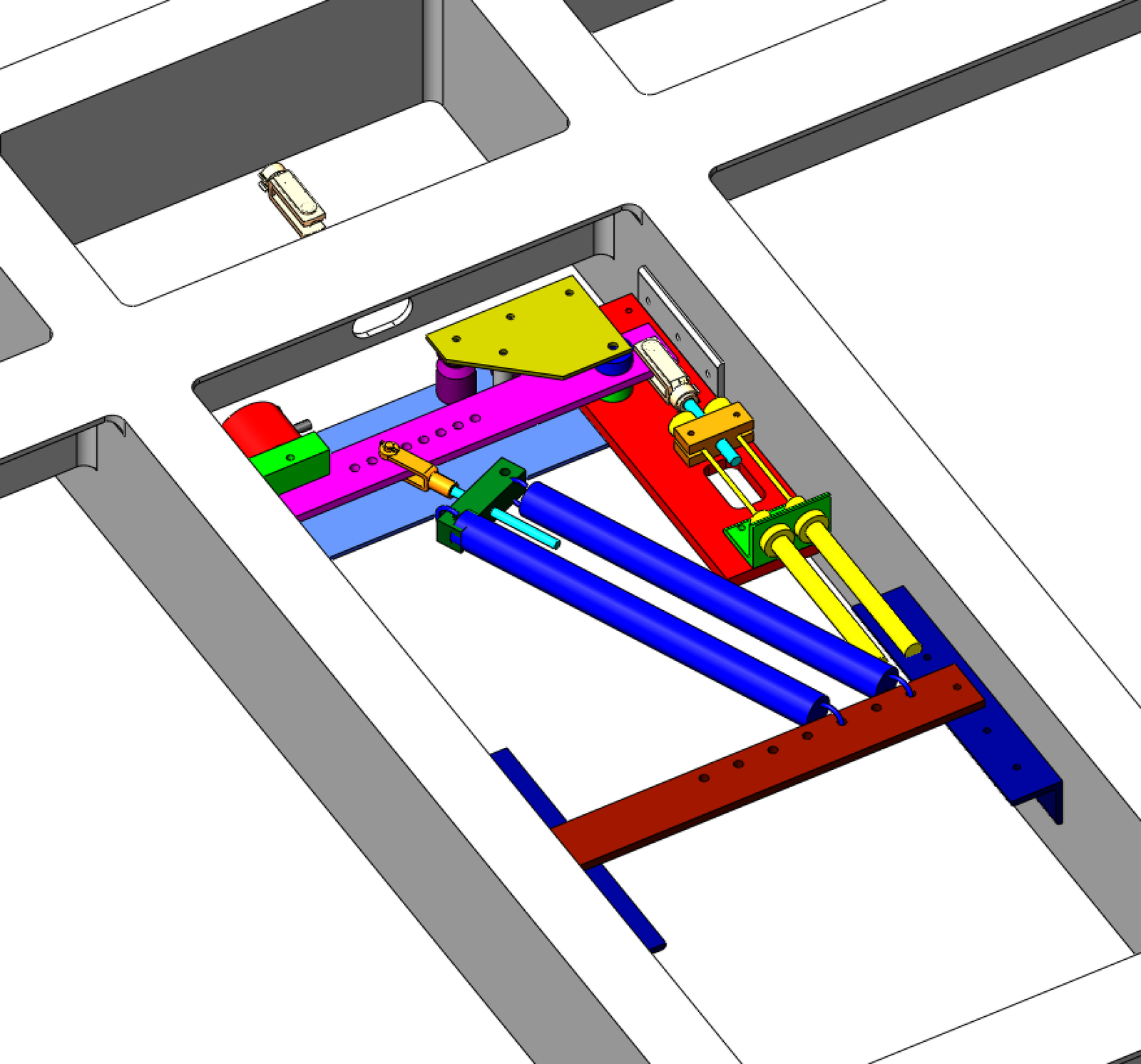
An electromagnet (red) holds a steel block (green) on a spring-loaded arm (magenta) with 6:1 mechanical advantage. Cut the power and the springs pull both brake cables (yellow) with about 500 lb, fully braking; unpowered, it simply acts as the parking brake. The old parking-brake lever resets the arm onto the magnet, and turnbuckles keep everything adjustable. The embedded system decides when to cut that power.