Overview
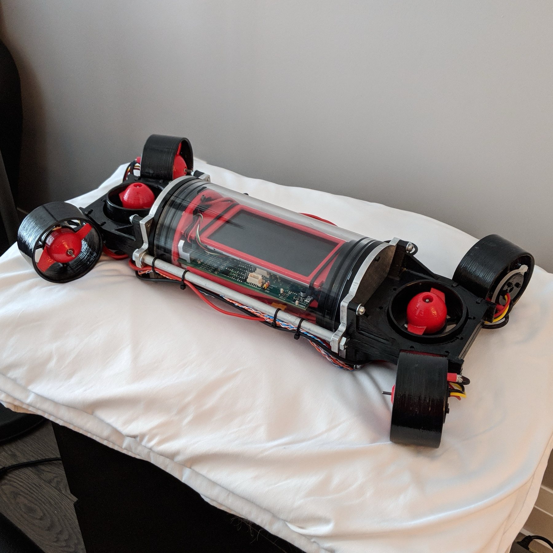
As a team of four we built, in three and a half months, an underwater autonomous torpedo to race through an underwater obstacle course. Everything was built for autonomy from the ground up: the mechanical system, the embedded system and the software.
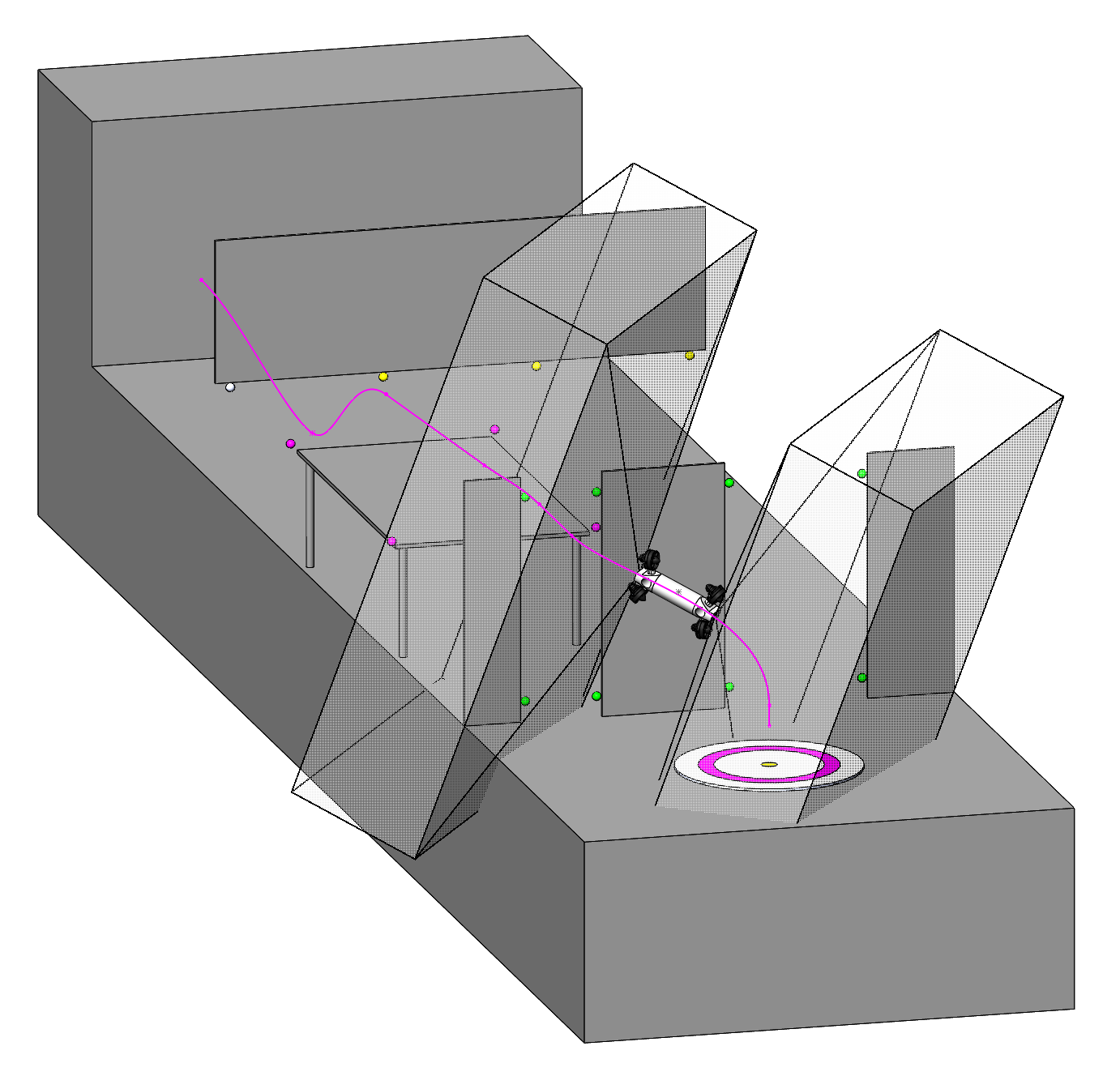
In the render of the course, the vision targets are the coloured balls and the vehicle’s fixed path is the magenta line.
As team lead I defined the scope from an analysis of the competition and our timeline, and I independently developed the vehicle’s autonomy stack.
System architecture
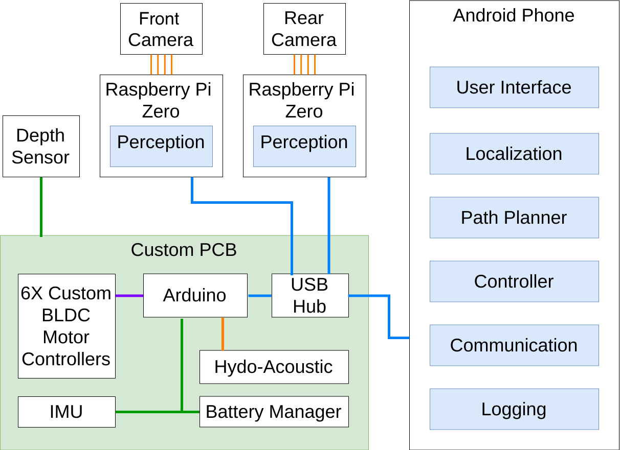
- Two fisheye cameras, front and rear, each with a dedicated Raspberry Pi running perception to locate vision targets (golf balls) along the course.
- Perception results, plus IMU and depth data, go over USB to an Android phone that runs the autonomy stack.
- The stack’s desired thrust for each of the six thrusters goes to the embedded system on a custom PCB.
- Six custom sensored brushless motor controllers turn desired thrust into motor commands using thrust maps calibrated offline.
- The thruster layout lets the vehicle translate and rotate freely in all six degrees of freedom.
Autonomy stack
ROSJava on the phone gave us flexible code plus ROS’s visualization and networking tools with little infrastructure. Each Raspberry Pi processes its camera with OpenCV and sends target positions in the vehicle’s body frame.
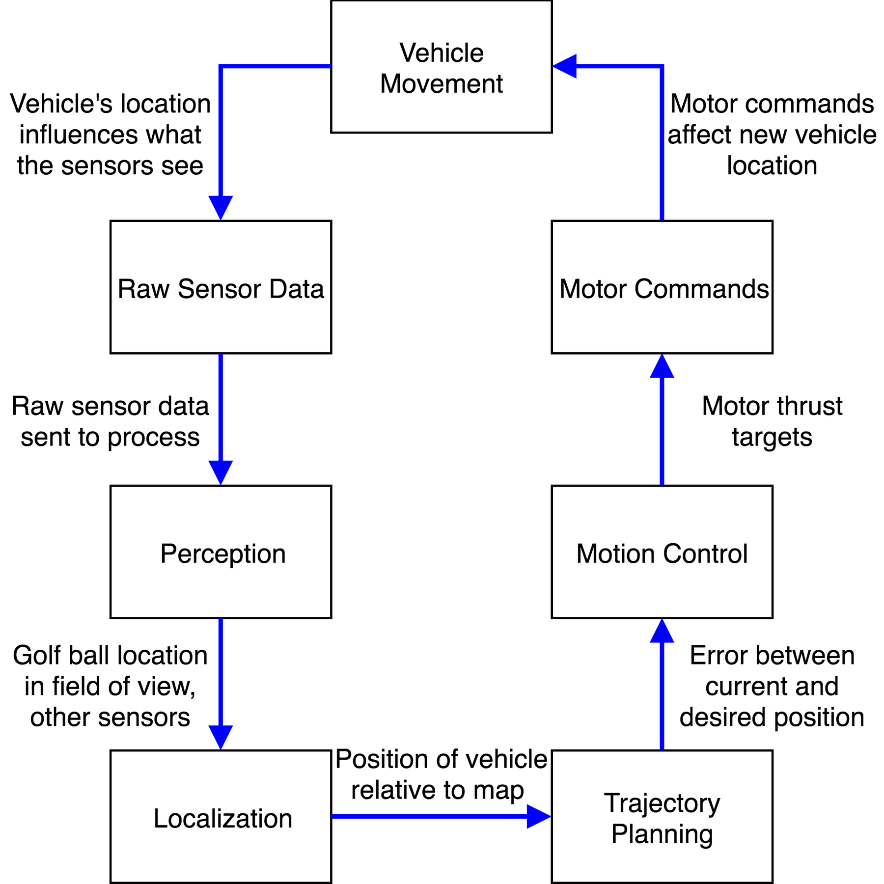
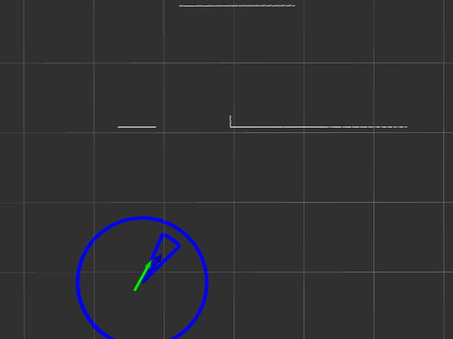
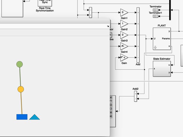
A particle filter fuses those detections with orientation and depth. Scan registration against a map of known target locations sharpens both the particle weights and their propagation. With the vehicle located, pure pursuit picks the next pose along a fixed, pre-computed optimal path that takes the vehicle safely through the course, and a closed-loop LQR controller with an integrator commands the thrusters to minimize tracking error.
Autonomy stack
- SensingFisheye cameras ×2OpenCV target detection on Raspberry PisIMU + depth sensor
- LocalizationParticle filterScan registration against a map of vision targets
- GuidancePure pursuitAlong a pre-computed optimal trajectory
- ControlLQR + integratorMultivariable, minimizes tracking error
- Actuation6 motor controllersCustom brushless, calibrated thrust maps6 thrusters