The idea
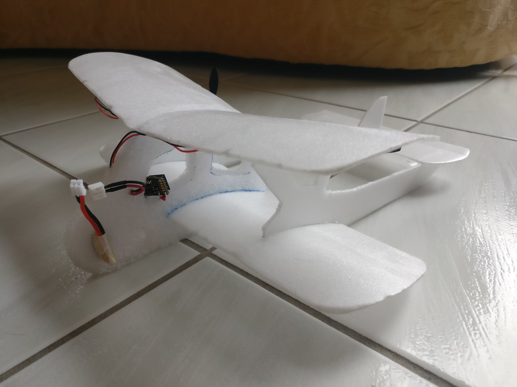
I’ve grown up around radio-control planes, helicopters, boats and cars. When quadcopters got small enough to fly indoors, my dad wondered whether a plane could too, with no servos or control surfaces at all: just two motors, using differential thrust to turn and throttle to climb.
Off-the-shelf controllers were bigger than they needed to be, and the 0.28 g receiver we chose needed at least 3.7 V while the battery could sag to 3 V. There was no simple existing solution, so I designed one.
Requirements
- Map two receiver channels to the share of battery voltage applied to two independent motors.
- Handle 2 A to the motors at up to 4.2 V.
- Run from a one-cell LiPo (2.5–4.2 V) while supplying the receiver with 500 mA at 3.7–4.2 V (4.2 V is the limit for the small servos later planes might use).
- Monitor battery voltage and flash an LED below a calibrated threshold.
- Break out spare receiver channels, and be as small and light as possible.
Design
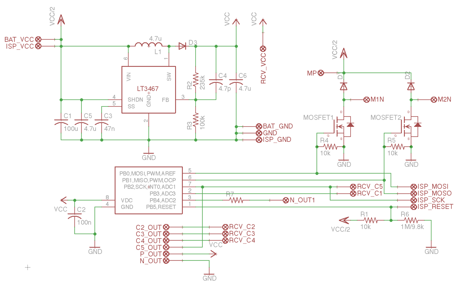
The ATtiny85’s timer 1 offers phase-correct PWM on two pins with independent compare values, ideal for driving two MOSFETs at different duty cycles. Timer 0 times the receiver’s 50 Hz, 1–2 ms pulses, captured on edge interrupts (one on the interrupt pin, one via pin-change).
With only six I/O pins, the ISP programming pins double as I/O, and the reset pin reads battery voltage through a divider that keeps it above the 2.5 V reset threshold. A boost converter regulates the receiver and chip to 4.2 V; that section can even be snapped off and reused on its own.
In the schematic, the boost converter (an LT3467) is at top left and the two MOSFET motor outputs are at top right. The ATtiny85 sits at bottom left, with the divider feeding its reset pin (R1 and R6) at bottom right.
Signal path
- InputRC receiver0.28 g · 50 Hz pulses, 1–2 ms wide
- DecodePulse timingTimer + pin-change interrupts
- OutputPhase-correct PWMTwo independent channels
- DriveMOSFETs → motorsDifferential thrust
Result
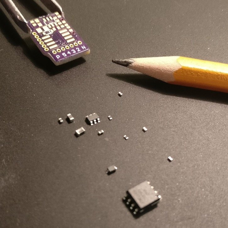
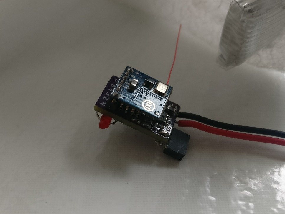
The finished board weighs 0.5 g, with the receiver plugged in on top. The first plane to use it (pictured at the top) weighs 20 g in total and flies easily around a large basement.