Why
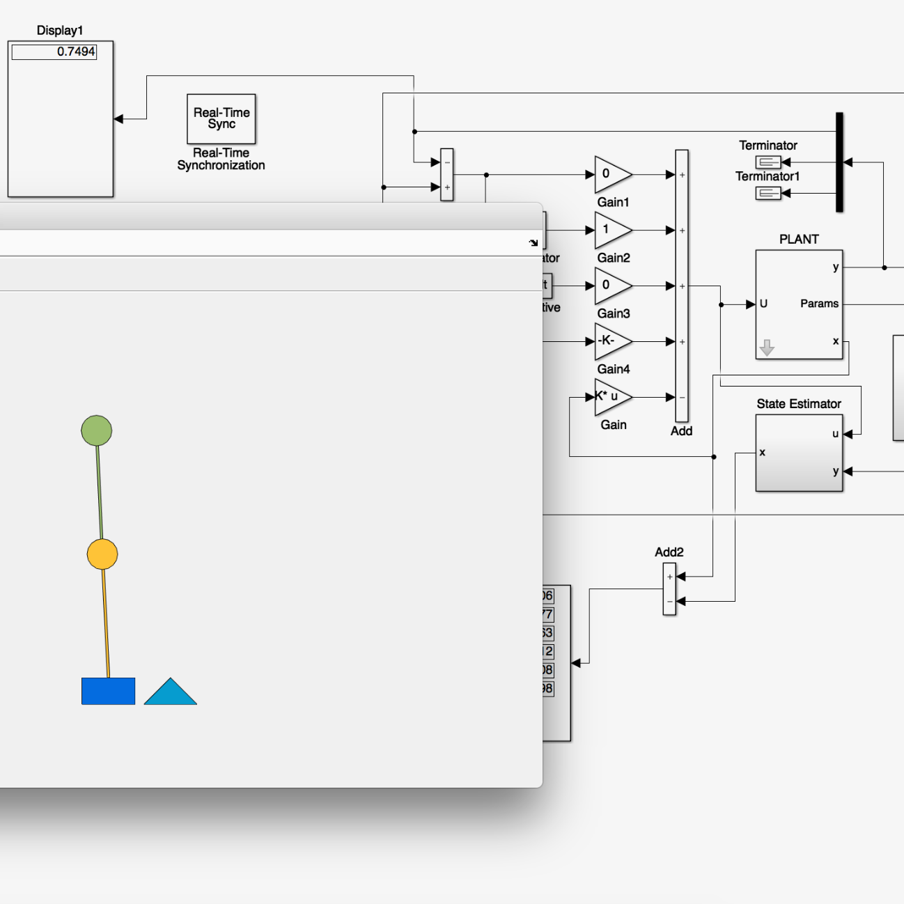
At Embark I had started designing software-in-the-loop and hardware-in-the-loop testing, and I wanted to keep learning how to model physical systems in Simulink. This began as a small experiment to model and animate a double pendulum, a classic demonstration of chaos.
Controller
Once the animation worked, I wanted to know how hard it would be to balance the pendulum inverted. A simple LQR controller did it, and was surprisingly robust, as long as it had perfect state information.
Realistic sensing
So I made the simulation realistic. I analysed the output of an off-the-shelf gyro in Matlab and reproduced its noise profile and bias in Simulink, then used that model for the angular-rate feedback of both pendulum stages.
To give the LQR controller a state estimate, I designed a Kalman filter using a model linearized about the balanced position and the modeled gyro feedback. With that observer, the controller balanced the pendulum comfortably, which was enough to conclude that a physical build with the same sensors would work.
Estimation and control loop
- GoalUpright reference
- ControlLQR controller
- PlantDouble pendulumNonlinear Simulink model
- SensingModeled gyrosNoise and bias fitted to a real sensor
- EstimationKalman filterLinearized about upright
↺ state estimate