Why build one
When consumer FDM printers took off, most under $3,000 had problems with reliability, speed, number of extruders or printable materials. I spent a long time on enthusiast forums collecting the best techniques and parts, then mocked up my own design with a manufacturing plan, bill of materials and budget.
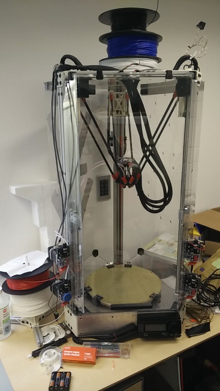
I machined most parts in the University of Waterloo’s student machine shop and printed some on the school’s industrial printer. It was working within about three months, and I kept improving it for a year. It has since printed dozens of rolls of filament, including parts for Varden Labs and Embark, and it printed perfectly first time after a 3,500 km drive in the back of a pickup.
Design details
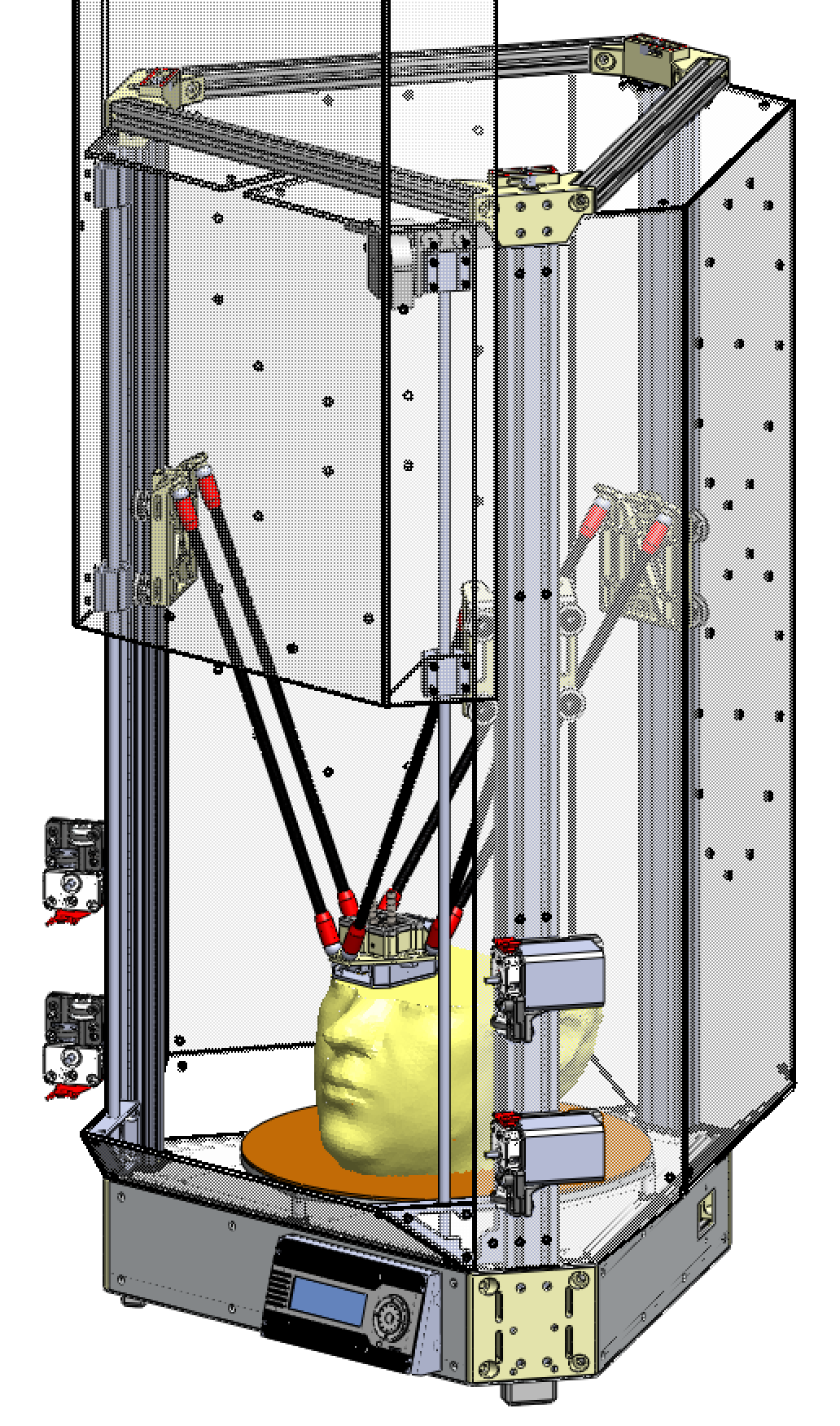
- Magnetic ball linkages. Each of the three carriages connects to the print head through links with a ball joint at each end. Instead of cup-and-ball joints, rare-earth magnets in low-friction Acetal cups hold steel balls. There’s no backlash; wear just shortens the links slightly, which software can absorb; and a jam pulls them apart instead of breaking something.
- Four independent extruders, each with its own feed and heater, plus a fan that quickly cools an idle nozzle by about 30 °C so it doesn’t ooze onto the print.
- Heated bed stack-up: quarter-inch cast aluminium (which doesn’t warp), a silicone AC heater on a thermal fuse, borosilicate glass with PEI or garolite depending on the plastic, and PEEK standoffs isolating it from the frame.
- Belt tension set with thin ratcheting zip-ties looping each belt to its carriage, which keeps it light, adjustable and trivial to service. All three belts need similar tension, since tensioning stretches them slightly.
- Water cooling for the extruders and the stepper motors, with a pump and radiator in the base. To stop clogs, only a short length of filament is kept hot and the rest is cooled, and water cooling does that in a compact extruder.
- A polycarbonate enclosure with a spring-counterbalanced sliding door, to keep parts from warping.
Calibration
A delta printer’s weakness is calibration: small errors in link length, belt stretch, frame bending or end-stop position make the nozzle travel a curved surface instead of a plane, which ruins first layers. You can measure the gap with shims, but the measurements don’t map directly to the tuneable parameters.
So I built an Excel and VBA tool that simulates the height map each kind of error would produce, finds the error model that best matches the measurements, and gives the calibration offsets directly. It made calibration dramatically easier.
In the screenshot, the ideal geometry and the error model’s values run along the top. The circle is the simulated height map across the bed: green is on the plane, and red and dark blue are 0.05 mm off in either direction.
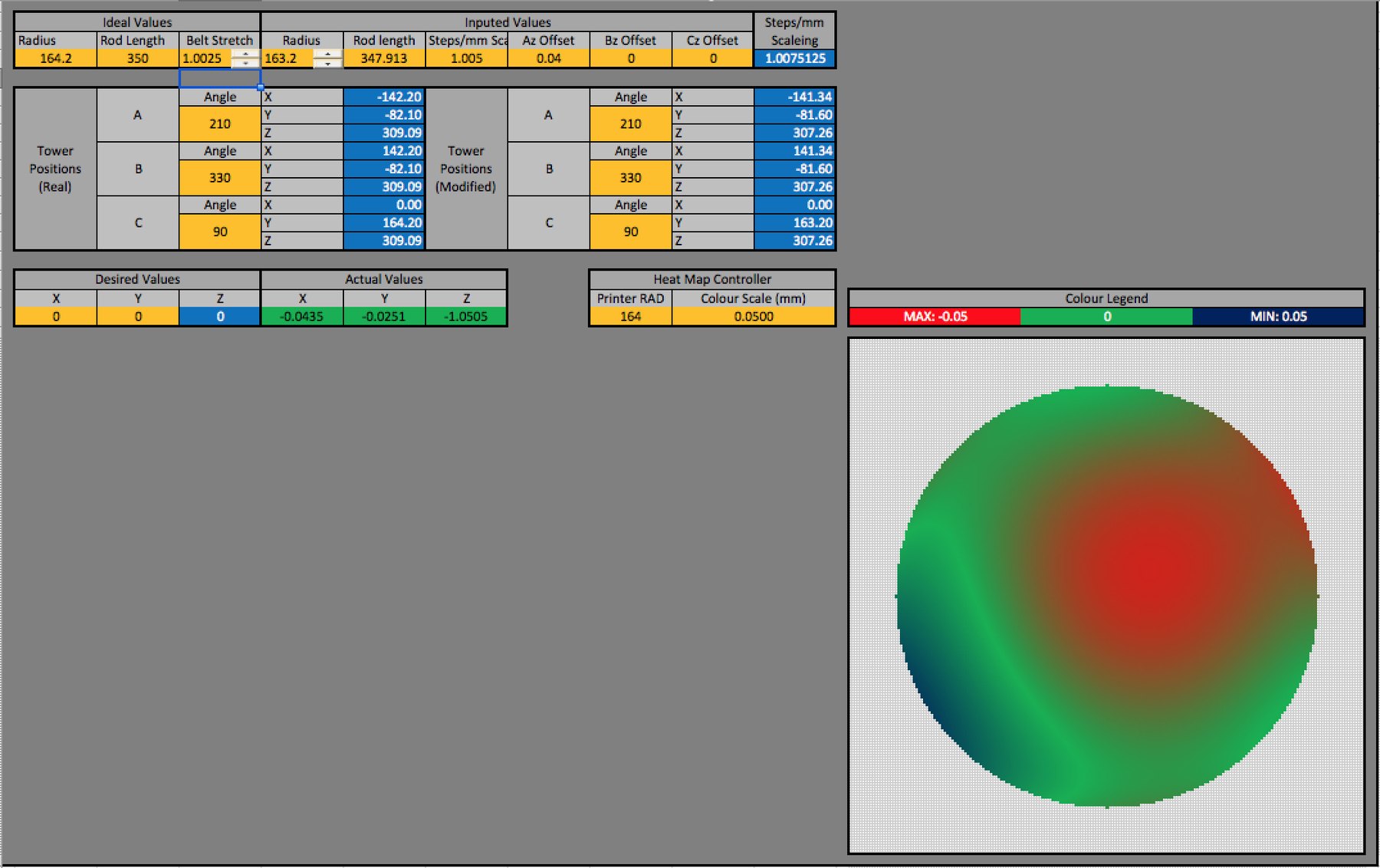
Calibration tool
- MeasureShim measurementsNozzle-to-bed gap across the bed
- ModelSimulated heat mapsExcel + VBA, under candidate error models
- FitBest-fitting modelLinkage length, belt stretch, end-stop offsets…
- ApplyCalibration offsetsEntered into firmware